Printable: Page 1 (pdf) | Page 2 (pdf) | Page 3 (pdf)

Type n
ANTI-CONDENSATION HEATERS
FOR ELECTRIC MOTORS & GENERATORS

The ACH/n range of electric heating tapes provides low cost protection against condensation within rotating electrical equipment. Typical applications would be electric motors, generators and alternators which operate in damp or wet conditions. Examples would include off shore, shipboard and marine equipment, dockside cranes, well pumps and all equipment operating in a tropical environment. Specifying anti-condensation heaters at the design stage can save the expense of costly rewinds and down time.

FITTING RECOMMENDATIONS

The heating unit is designed for the inclusion in the impregnation process.

A motor heater is usually sized to fit around the stator pack, covering at least 70% of the circumference.

When a heater is selected that is longer than the circumference care must be taken to keep the overlap separated from the original turn by 5mm minimum to avoid hot spots.

A separate terminal block is usually provided for the heater units. A change-over contact wired to bring in the heater when the motor is de-energized must be provided on the starter.

RETRO FITTING OF HEATERS

By then OEM or a Rewinder on a stock motor:


The heater should be bound on the windings, as described page 2/3, then heavily coated with varnish and allowed to

Anti Condensation Heater ACH/n

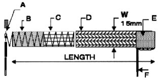
A. High quality dip soldered joint.
B. 80/20 Ni Cr or heating element. Glass fibre tape carrier.
C. Polyester backed adhesive tape insulation.
D. Glass fibre braid insulation.
E. Acrylic adhesive backed glass fibre tape insulation and cold leads reinforcement.
F. 500mm ColdLeads 19/0.15 ETFE(Tefzel) insulated equipment wire.


ACH/n

cure and then a second coat applied, to ensure that the heater and windings form a homogenous mass to provide good thermal conductivity.

By a Rewinder:

As part of the rewind process, where the heater will be fully impregnated with the windings.

ACH/n Range
ACH Ref Length Volts Watts
in mm
0a
0b
1a
1b
2a
2b
4a
4b
5a
5b
6a
6b
7a
7b
8a
8b
12
12
17
17
27
27
30
30
40
40
42
42
58
58
67
67
305
305
432
432
686
686
762
762
1016
1016
1067
1067
1473
1473
1702
1702
110
240
110
240
110
240
110
240
110
240
110
240
110
240
110
240
9
9
12
12
20
20
22
22
29
29
30
30
42
42
48
48

APPROVALS:
BASEEFA Component Approval No. Ex 94Y4457U
Code: Ex N II
BASEEFA Component Approval No. Ex 98Y4345U to EN 50021: 1998 Code: EEx nA II

ATEX Certificate No. BAS02ATEX3153U
The component is coded: Coded Ex II 3G EEx nA II


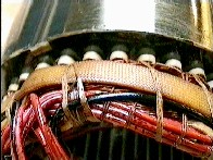
FITTING INSTRUCTIONS

1) Accommodating Standard Length Motor Heaters

The heating unit is designed for inclusion in the impregnation process.

It is possible to apply Type ACH/n heaters to a number of different winding diameters on the principle that the length of a particular heating unit or units will cover at least 70% of the circumferential distance and if an overlap occurs, that the client will ensure 5 mm separation between the adjacent turns of the heating unit.

Large electric motors may require a number of heaters on each end of the stator pack, but very large motors have the advantage that the surface to which the heaters must be fitted is reasonably smooth and continuous which improves the heat transfer efficiency.

Thus a number of heaters may be conveniently fitted at each end of a large motor, and any individual heater need only cover a semi-arc or a part circumference. In this case the heating units are usually fixed by pieces of adhesive-backed glass fibre electrical insulation tape placed across the heaters at convenient intervals.

2) Fitting of Motor Heaters

Usually motor heaters are laced onto the stator pack end turns during the manufacturing process. This is normal practice for smaller motors, but care must be taken to allow for the shrinkage of the lacing material during the impregnation process. Many polymer-based materials which are used in the construction of modern motors suffer severe contraction during the varnishing process which incorporates various heating cycles, and the tension thus created in the lacing at its final state may be sufficient to damage or cut-through the heating unit.

Alternative fixing methods use an adhesive-backed glass fibre electrical insulating tape of suitable temperature rating which is applied over the heating unit so as to fix the heating unit firmly in place. This adhesive tape must be considerably wider than the heaters.

Such fixing methods are relatively inexpensive and convenient and also suitable for retro-fit operations, provided the instructions given in 3) below are complied with.

On larger motors a number of heaters may be required on each end in order to provide the total nominal power input, and in this case, they may be fixed by overwrapping with adhesive tape as above, or by localised fixings with strips of adhesive tape placed across the width of the heater unit.

The heater shall be connected to earth while the motor windings is high voltage tested.

The heater shall be high voltage tested to earth at 2000V r.m.s. for 1 minute

3) Retro-fitting of Heaters

It should be noted that Type ACH/n motor heaters are the only semi-fabricated product made by RTL and they are designed as components for incorporation into the motor impregnation process. Thus if they are fitted later in the production programme, or are used as retro-fit devices, it is essential that two successive coats of varnish are applied by brush and allowed to cure before the units are commissioned in order to provide the necessary degree of thermal conductivity and moisture proofing to the heater.


Component Approval No. Ex 94Y4457U: Motors and generators that comply with BS 5000: Part 1b 1985 + Amendment 1 to 4.

Component Approval No. Ex 98Y4345U: Motors and generators that comply with EN 50021: 1998.

SCHEDULE OF LIMITATIONS

1. To achieve temperature class T3 without the need for testing:

  1. The heater element shall be closely bound to the motor end winding prior to impregnation with a suitable impregnating substance by dipping, trickling or vacuum impregnation.

    Coating by painting or spraying is not recognized as impregnation.

    The impregnation shall be carried out in compliance with the special instructions of the manufacturer of the relevant type of impregnating substance and in such a way that the space between the heater and winding are filled as completely as possible.

    If impregnating substances containing solvents are used, the impregnation and drying processes shall be carried out at least twice.

  2. The motor winding shall be of the "round wire " type with no insulation between the motor winding and the heater other than the integral varnish insulation of the wire.

  3. When more than one heater is fitted to an end winding, or when the length of the heater is greater than the circumference of the end winding, adjacent turns shall have a radial clear- ance of at least 5mm.

  4. The maximum rated supply voltages are,110 volts for ACH/n/a and 240 volts for ACH/n/b. They are designed for motors with maximum winding temperatures of 140 øC measured by change of resistance (equivalent to 100 øC temperature rise in 40 øC ambient).

2. The heater shall be connected to earth while the motor winding is high voltage tested.

The heater shall be high-voltage tested to earth at 2000V r.m.s. for 1 minute.

Data Sheet 05/02
Current: Yes
Obsolete: No
Controlled Document

Anti-Condensation | Electric | Silicone | Sacrificial | Drum | Prices

Home Page | Top of page

Resistance Technology Limited, 8 Worrall Street, Salford,
MANCHESTER, M5 4TH, ENGLAND, UK.

Tel +44 (0)161 877 7345: Fax +44 (0)161 877 8711

http://www.resistance-technology.co.uk